
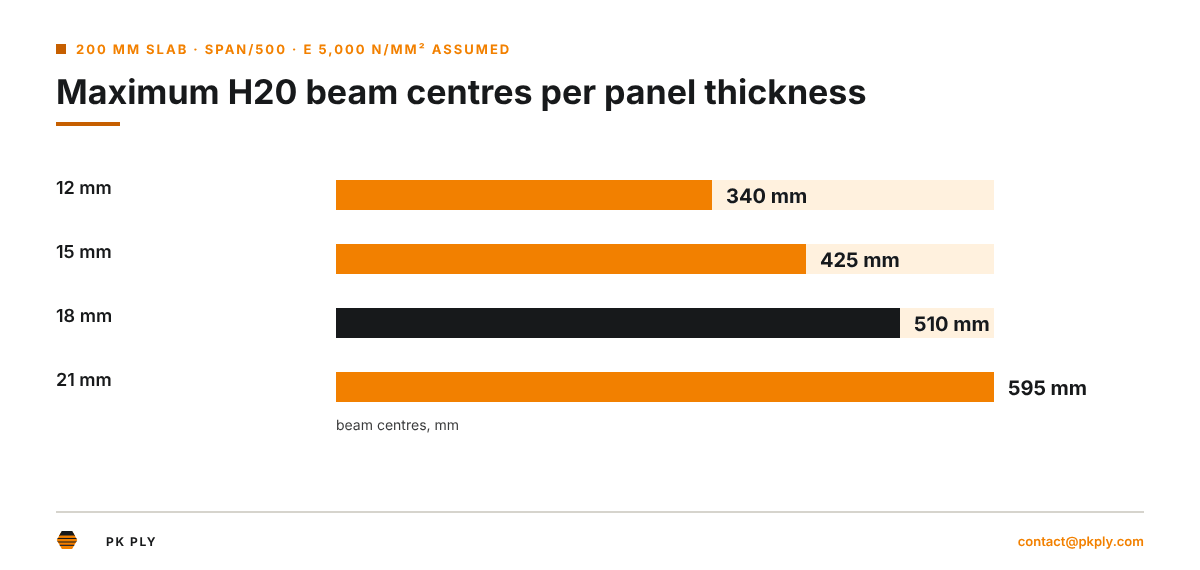
On an H20 beam deck, the beam centres decide the plywood: under a 200 mm slab, 18 mm film-faced panels suit centres up to about 510 mm and 21 mm panels about 595 mm at a span/500 limit. A wrong pairing shows as sag lines in the soffit or a deck that needs extra beams. PK Ply presses the deck sheet, not the beam.
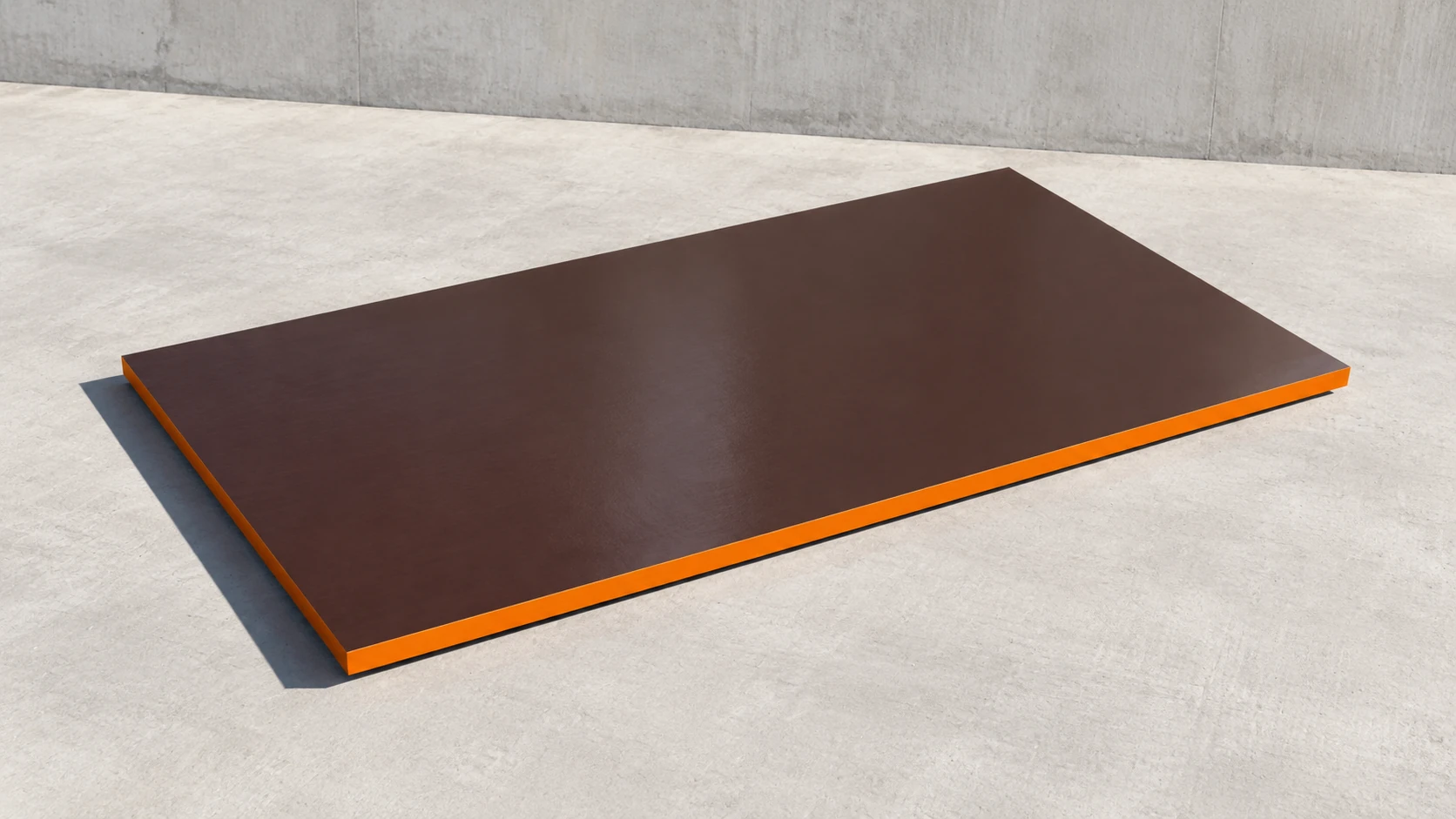
What thickness plywood goes on H20 beams for a slab?
For a typical 200 mm slab on H20 beams, use 18 mm film-faced plywood at beam centres up to about 510 mm and 21 mm at up to about 595 mm, holding deflection to span/500. Thinner 12 and 15 mm panels work only at closer centres or under thinner slabs. Every figure here rests on the assumptions stated below.
The pairing works in both directions. A contractor who already owns a stock of H20 beams and a drop-head grid will find the beam centres fixed and choose the panel thickness to suit. A contractor buying a new deck can choose the thickness first and set the beam centres from it. Either way, the deck sheet and the beam centres are one decision, and the sheet length has to fit it too (see the sheet module section below).
| Panel thickness | Max beam centres, 200 mm slab, span/500 | Max beam centres, 200 mm slab, span/300 | Where it fits |
|---|---|---|---|
| 12 mm | About 340 mm | About 400 mm | Edge strips, infill between drop heads, thin slabs |
| 15 mm | About 425 mm | About 500 mm | Thin slabs, decks with close beams |
| 18 mm | About 510 mm | About 605 mm | The standard slab deck at 488 or 500 mm centres |
| 21 mm | About 595 mm | About 705 mm | Wide centres, thick slabs, exposed soffits |
Read the table as a planning guide for the panel order. Your formwork designer sets the final layout from the system supplier’s documents and the project’s own loads. What we control is the panel: its build, its thickness within ±0.5 mm and its edges, all written on the order’s technical sheet.
What is an H20 beam, and what does the plywood deck do on it?
An H20 beam is a prefabricated timber formwork beam 200 mm deep, with solid softwood flanges top and bottom and a glued web between them. On a slab deck, rows of H20 beams sit on primary beams or drop heads carried by props, and the plywood deck sheet spans from beam to beam and takes the wet concrete.
In Europe these beams have their own product standard. EN 13377 covers prefabricated timber formwork beams: requirements, classification and assessment. The beam is a formwork system part, bought from a system or beam supplier with a load chart. We do not make beams; our two mills in Chi Linh, Hai Phong make the film-faced plywood that sits on them.
A published H20 data sheet gives a beam height of 200 mm and a width of 80 mm, with permissible values for bending moment and shear force. Its figures, which we use for the beam check further down, are these:
| H20 beam property (published data sheet) | Value |
|---|---|
| Height and width | 200 mm × 80 mm |
| Permissible bending moment | 5.0 kNm |
| Permissible shear force | 11.0 kN |
| Moment of inertia | 4,613 cm⁴ |
| Modulus of elasticity | 10,000 N/mm² |
| Weight of a 2.45 m beam | 12.25 kg, about 5 kg per metre |
The plywood does three jobs on this deck:
- It spans between the beams. The sheet works as a continuous plate over several beams, and its stiffness decides how far it sags between them under wet concrete.
- It forms the soffit. The film face is the mould for the underside of the slab, so every sag, step at a joint and open hole prints on the concrete.
- It is the working floor. Steel fixers and the pour crew walk on it, so it carries people and equipment before and during the pour.
The engineering assumptions behind our numbers
Our beam-centre and deflection figures rest on five stated assumptions. Fresh reinforced concrete weighs 26 kN/m³, the deck adds 0.1 kN/m², and a working load of 1.5 kN/m² enters the strength checks only. The plywood has an effective E of 5,000 N/mm² along the face grain and runs continuous over three or more spans.
| Assumption | Value we use | Where it comes from |
|---|---|---|
| Fresh reinforced concrete | 26 kN/m³ | 24 kN/m³ concrete, plus 1 for reinforcement and 1 for unhardened concrete |
| Deck self-weight | 0.1 kN/m² (0.2 kN/m² with beams) | 18 mm plywood at about 580 kg/m³, plus beams at about 5 kg per metre |
| Working load, strength checks only | 1.5 kN/m² | People, equipment and heaping during the pour |
| Plywood stiffness along the face grain | E of 5,000 N/mm² | Planning value; replace with the declared value |
| Span model | Continuous over three or more spans | Deflection coefficient 0.0069 |
| Deflection limits | Span/300 and span/500 | General and exposed-concrete limits in common use |
Loads. EN 1991-1-1 covers the specific weight of materials, self-weight of construction works and imposed loads for buildings. We take normal-weight concrete at 24 kN/m³, add 1 kN/m³ for reinforcement and 1 kN/m³ for unhardened concrete, and use 26 kN/m³ for the wet slab.
A 200 mm slab then weighs 5.2 kN/m², plus 0.1 kN/m² for the plywood itself. Part 1-6 of Eurocode 1 deals with actions on structures during execution. For the strength checks we add 1.5 kN/m² for people, equipment and heaping during the pour; deflection uses the concrete and self-weight only, because the soffit sets as the concrete sets.
Plywood stiffness. EN 636 gives a classification system based on bending properties, and the values it lists are not characteristic values to be used in design calculations. Design values come from a different standard.
EN 12369-2 provides characteristic values for plywood complying with EN 636 in bending, tension, compression, panel shear and planar shear. It applies to panels of 5 layers or more and 6 mm overall thickness and more, made of species with a mean density greater than 350 kg/m³ and not exceeding 750 kg/m³. Our Acacia and Eucalyptus cores, at planning densities of about 580 and 650 kg/m³, sit inside that range.
We work every table with an effective E of 5,000 N/mm² parallel to the face grain. This is a planning assumption, not a test value for a given sheet. Replace it with the value on the declaration of performance for the panel you order. Deflection scales with 1/E: at 4,000 N/mm² every deflection grows by 25% and the maximum beam centres shrink by about 7%.
Span model and limits. The sheet is treated as a plate continuous over three or more beams, with a maximum deflection of 0.0069 × q × L⁴ / (E × I), where I is the second moment of area of a 1 m strip, 1000 × t³ / 12. We check span/300, a common general limit, and span/500, a common limit for exposed concrete. The project’s surface class decides which one applies.
Who designs the deck. EN 12812 does not specify requirements for formwork, and it does not provide information about timber formwork beams conforming to EN 13377 or props conforming to EN 1065. In the UK, BS 5975-2:2024 gives recommendations and guidance on design, specification, construction, use and dismantling of falsework. Your temporary works designer applies those rules. Our tables help you choose the panel before that design is final.
Deflection per thickness at common H20 beam centres
Under a 200 mm slab, 18 mm plywood deflects about 0.94 mm between H20 beams at 500 mm centres and 21 mm plywood about 0.59 mm, both inside span/500. At 625 mm centres the 18 mm sheet reaches about 2.30 mm, past span/300, while 21 mm stays at about 1.45 mm.
The table gives the calculated mid-span deflection for each of our four everyday thicknesses at four beam centres. Load: 5.3 kN/m² (200 mm of concrete at 26 kN/m³ plus the deck). Stiffness: E of 5,000 N/mm², sheet continuous over three or more spans.
| Beam centres | 12 mm | 15 mm | 18 mm | 21 mm | Span/500 limit | Span/300 limit |
|---|---|---|---|---|---|---|
| 300 mm | 0.41 mm | 0.21 mm | 0.12 mm | 0.08 mm | 0.6 mm | 1.0 mm |
| 400 mm | 1.30 mm | 0.67 mm | 0.39 mm | 0.24 mm | 0.8 mm | 1.33 mm |
| 500 mm | 3.17 mm | 1.63 mm | 0.94 mm | 0.59 mm | 1.0 mm | 1.67 mm |
| 625 mm | 7.75 mm | 3.97 mm | 2.30 mm | 1.45 mm | 1.25 mm | 2.08 mm |
Two patterns stand out. Deflection grows with the fourth power of the span, so going from 500 to 625 mm centres multiplies it by about 2.4. It falls with the cube of the thickness, so 21 mm is about 1.6 times as stiff as 18 mm on the same beams. That is why a 3 mm thicker sheet can carry a beam spacing that is 85 mm wider.
Bending stress is rarely what limits a plywood deck on H20 beams. At 500 mm centres under 6.8 kN/m², the concrete plus the 1.5 kN/m² working load, an 18 mm sheet carries a bending moment of 0.1 × q × L² and a stress of about 3.1 N/mm² in a 1 m strip. Your designer compares that with the design strength from the declaration of performance; for most decks, the deflection limit is reached first.
A single-span offcut behaves differently from a sheet over many beams. A piece that spans only one bay deflects with a coefficient of 5/384 instead of 0.0069, close to twice as much. Put an extra beam under narrow infill pieces, or cut them so they reach across at least two bays.
Maximum H20 beam centres by slab depth and finish
Maximum beam centres fall as the slab gets thicker: 18 mm plywood reaches about 560 mm under a 150 mm slab at span/500, but only about 445 mm under a 300 mm slab. For an exposed soffit and a thick slab, 21 mm on 488 or 500 mm centres keeps the deck within span/500 up to about a 300 mm slab.
The table solves the deflection formula for the beam centre that just meets each limit. Values are rounded down to the nearest 5 mm. Same assumptions as above: 26 kN/m³ concrete, 0.1 kN/m² deck, E of 5,000 N/mm², continuous sheet.
| Slab depth | Limit | 12 mm | 15 mm | 18 mm | 21 mm |
|---|---|---|---|---|---|
| 150 mm | Span/500 | 370 mm | 465 mm | 560 mm | 650 mm |
| 150 mm | Span/300 | 440 mm | 550 mm | 660 mm | 775 mm |
| 200 mm | Span/500 | 340 mm | 425 mm | 510 mm | 595 mm |
| 200 mm | Span/300 | 400 mm | 500 mm | 605 mm | 705 mm |
| 250 mm | Span/500 | 315 mm | 395 mm | 470 mm | 550 mm |
| 250 mm | Span/300 | 370 mm | 465 mm | 560 mm | 655 mm |
| 300 mm | Span/500 | 295 mm | 370 mm | 445 mm | 520 mm |
| 300 mm | Span/300 | 350 mm | 440 mm | 525 mm | 615 mm |
The table answers the slab question from the beam side as well. A contractor with beams set at 500 mm centres under a 250 mm slab and an exposed soffit needs 21 mm panels: 18 mm stops at about 470 mm. Under a 150 mm slab at the same centres, 18 mm has room to spare, while 15 mm falls short at about 465 mm.
The formula behind the table is L = (E × I / (0.0069 × q × k))^(1/3), where k is 300 or 500. You can rerun it with your own E from the declaration of performance, or use our formwork panel span calculator to try thicknesses and spacings against your load.
How far can H20 beams span between props?
With the data-sheet values above and beams at 500 mm centres, an H20 beam under a 200 mm slab can span about 2.95 m between primary beams or props at a span/500 limit; at 400 mm centres about 3.20 m. Beam deflection, not bending, governs at these loads. The beam supplier’s load chart decides the real figure.
This is a check on the beam, which is your formwork supplier’s product, not ours. We include it because the panel choice moves it: closer beam centres for a thinner sheet put less load on each beam, so each beam can span further between props.
We worked it as a single span with the load per beam w = q × beam centres. Bending is checked against the permissible moment of 5.0 kNm and shear against 11.0 kN. Deflection is checked at span/500 with EI of 10,000 N/mm² × 4,613 cm⁴, and the deck and beams add 0.2 kN/m² of self-weight.
| Slab depth | Beam centres 400 mm | Beam centres 500 mm | Beam centres 625 mm |
|---|---|---|---|
| 150 mm | About 3.50 m | About 3.25 m | About 3.00 m |
| 200 mm | About 3.20 m | About 2.95 m | About 2.75 m |
| 250 mm | About 2.95 m | About 2.75 m | About 2.55 m |
| 300 mm | About 2.80 m | About 2.60 m | About 2.40 m |
Bending would allow longer spans: about 3.41 m for 500 mm centres under a 200 mm slab against the 2.97 m that deflection allows. A beam continuous over a primary beam deflects less than our single-span model, and shear deformation of the web, which we ignore, adds a little. These are the reasons to use the supplier’s chart for the prop grid and this table only as orientation.
The formwork prop under the primary beams is a separate part again. Props have their own standard, EN 1065, and their capacity depends on the extension; we do not size them here.
Which sheet size suits an H20 beam deck, 1220 × 2440 or 1250 × 2500?
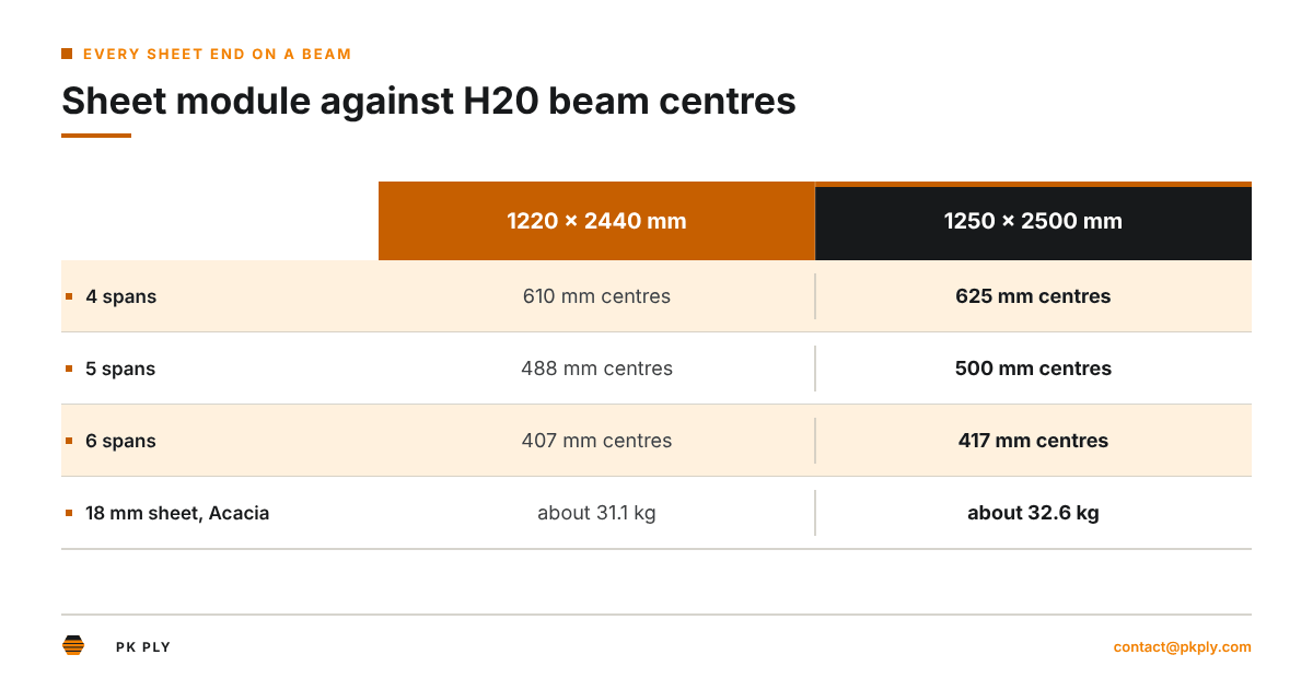
Both sizes work on an H20 beam deck if the beam centres divide the sheet length, so every sheet end lands on a beam. A 1220 × 2440 sheet fits 610, 488 or 407 mm centres; a 1250 × 2500 sheet fits 625, 500 or 417 mm centres. Pick the size whose module matches the centres your thickness allows.
| Spans per sheet | 1220 × 2440 mm: beam centres | 1250 × 2500 mm: beam centres | 18 mm plywood at span/500, 200 mm slab |
|---|---|---|---|
| 4 spans | 610 mm | 625 mm | Too wide for 18 mm at span/500; 21 mm reaches it under a 150 mm slab |
| 5 spans | 488 mm | 500 mm | Inside the 510 mm limit for 18 mm |
| 6 spans | 407 mm | 417 mm | Comfortable for 18 mm; also inside the 425 mm limit for 15 mm |
The 1250 × 2500 mm sheet is the common European formwork size, and the 500 mm centre it gives with five spans is a round figure that many slab systems already use. The 1220 × 2440 mm (4 × 8 ft) sheet is the common size in North America, the Gulf, Africa and Asia, and its 488 mm module suits imperial decks laid at about 19.2 inches. We press both sizes at our mills; nothing larger than 1250 × 2500 mm.
The sheet width runs along the beam, and the beam length does not have to be a multiple of it. Beams lap or butt over the primary beams at the prop grid, while the sheets simply run on. What matters along the beam is that the long edges of the sheets meet cleanly and that the beam ends are supported.
Face grain and sheet layout on the beams
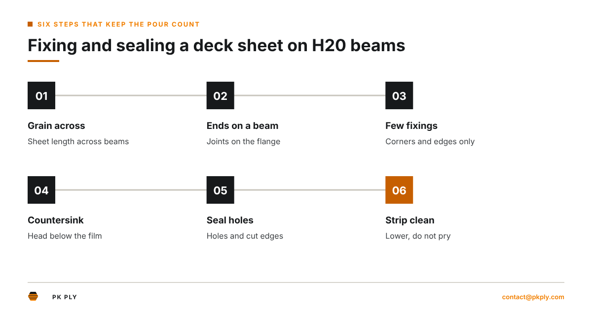
Lay each sheet with its length, and so its face grain, running across the H20 beams. Plywood is stiffer along the face grain than across it, and our deflection tables assume that orientation; a sheet turned the other way deflects noticeably more at the same centres.
The face veneers of our panels run along the sheet length, under the film, with the core veneers laid crosswise between them. On a beam deck that puts the outer plies, which do most of the work in bending, in the direction that spans between beams.
Four layout rules keep the deck flat:
- Ends on a flange. The end of every sheet sits on a beam. With an 80 mm flange and two sheets meeting on it, each sheet end bears on about 40 mm.
- Set out from the sheet, not only the drawing. Our sheets hold ±2 mm on length and width. Over a run of four sheets that can add up to about 8 mm, so check the beam positions against the laid sheets row by row.
- Stagger only where the design allows. Staggered end joints help spread the load at joints, but every staggered end still needs a beam under it.
- Infill last. Lay full sheets first, then cut infill pieces to the gaps at columns, drop heads and slab edges.
Can panels be cut to match the beam and prop layout?
Yes. Besides 1220 × 2440 and 1250 × 2500 mm sheets, we cut panels to a cutting list on request, so infill strips, drop-head fillers and edge pieces arrive at size with their cut edges painted at the mill. The cutting list goes on the order’s technical sheet, beside thickness, glue and film.
Cutting at the mill has a practical advantage on a beam deck: every cut edge is sealed before the panel leaves the line. A strip cut on site, by contrast, opens the core along its whole length, and if it is not painted before the first pour, that edge starts taking water on day one.
What a cutting list should contain:
- the finished size of each piece and the quantity
- the face-grain direction for strips (along the strip, so it spans across the beams)
- the tolerance you need on the cut, if tighter than ±2 mm
- edge paint on all cut edges
- marking per piece if the deck is planned bay by bay
Our cut-to-size formwork panels page lists what the mill cuts and how it is packed. A deck plan from your formwork supplier is the best input: we read the bays and return the piece list with the build.
How should panels be fixed to H20 beams?
Fix film-faced panels to H20 beams with as few screws or nails as hold the sheet in place: at the corners and ends where the sheet sits on a flange, about mid-way into the 40 mm bearing. Countersink the heads just below the film and seal every hole. Many slab systems lay sheets loose between edge fixings.
Each fixing is a hole through the film, and each hole is a way for water into the core. The fewer there are, the less repair each pour needs and the longer the face stays sound. On decks with a perimeter edge form or a system of drop heads, many sheets are held by their neighbours and the concrete weight, and only the end sheets, strips and pieces at openings need fixing.
Where fixing is needed:
- Pre-drill and countersink so the head sits just below the film without crushing it.
- Fix through the bearing zone. With 40 mm of each sheet end on the flange, a fixing at about 20 mm from the sheet end is in the middle of its bearing.
- Screws rather than nails where panels will be lifted and relaid; a clawed nail tears the film around the hole.
- Keep fixings off the face area that forms an exposed soffit, where the architect will see each repair.
- Use the same positions on every reuse, so new holes are not added each time.
How should screw holes in film-faced plywood be sealed on a beam deck?
Seal each screw hole in film-faced plywood flush with the film, using a fast-curing sealant or filler made for formwork faces or a matching plug, after the screw goes in and again whenever it comes out. An open hole lets water into the plies under the film, raises a rim around the hole and prints on the next slab.
Water enters a film-faced panel only where the film or the edge paint is broken. A screw hole breaks both the film and the outer veneers, so it exposes end grain in a small ring. On the first pour, cement paste and water fill it. Over the next pours the wood around the hole swells, the film lifts at the rim, and the rim marks the soffit.
A sealing routine that holds up on site:
- Before the first pour: seal around each head after fixing, flush with the film.
- At stripping: clean out holes that are no longer used and fill them flush.
- Between pours: check the face for open holes and lifted rims, then seal or trim and seal.
- With the release agent: coat the sealed holes and the whole face before every pour.
The same rule applies to any cut through the film: a saw cut, a hole for a service pipe, a notch at a column. We paint all four edges of every panel at the mill; whatever is cut on site needs the same paint before the panel goes back into the deck.
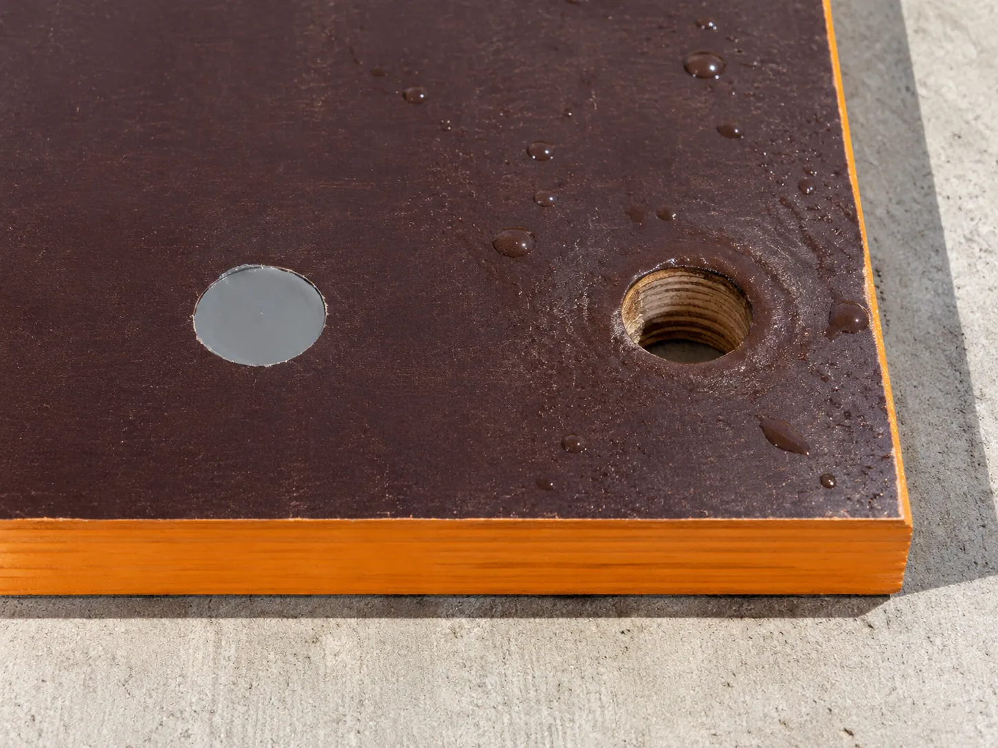
Does fixing to H20 beams cut the number of pours a panel gives?
Fixing to H20 beams does not have to cut the pour count, if the holes are few and sealed. Our MUF-glue panels give about 12–15 pours and phenolic-glue panels up to about 25, with proper handling, release agent on every pour and sealed edges, including cut edges and fixing holes. Unsealed holes and pried stripping are what shorten that life.
The pour count is a target for a panel build and a site, not a fixed property of the sheet. On a beam deck, four habits decide whether a panel reaches it:
- Holes: few fixings, the same positions on every reuse, each one sealed.
- Stripping: lower the deck on the props or drop heads and let the sheets come free; a bar driven between film and concrete scores the face and splits edges.
- Edges: reseal any chipped or cut edge before the next pour.
- Storage: stack panels flat and clean between pours, off the ground and out of standing water.
Budget film-faced panels typically give about 4–10 pours under the same care, because their glue spread and film are lighter. For the arithmetic of price per pour against pours expected on your programme, see our note on how many pours a panel gives, and the phenolic film-faced plywood page for the long-life build.
What thickness tolerance do our deck panels hold?
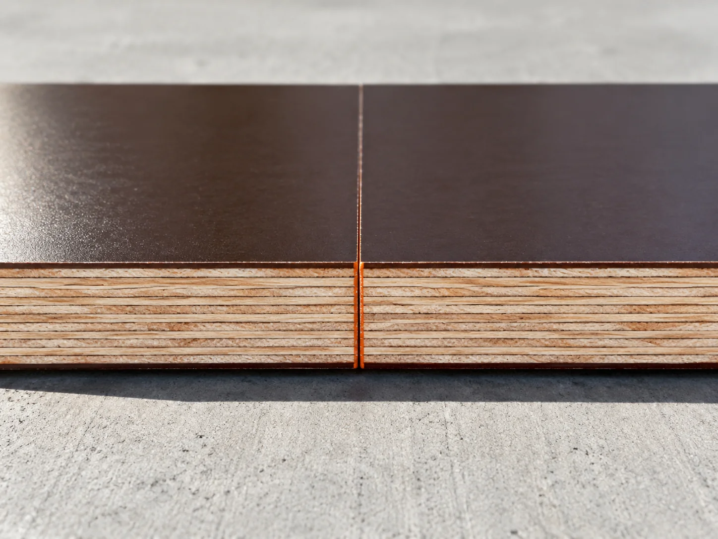
Our film-faced deck panels hold a thickness tolerance of ±0.5 mm, with ±2 mm on length and width, and the tolerance for each order is written on its technical sheet. On a beam deck, ±0.5 mm per sheet keeps the step between two sheets meeting on one beam at 1 mm or less.
| Dimension | Tolerance on our deck panels | What it means on H20 beams |
|---|---|---|
| Thickness | ±0.5 mm | Step at a joint of 1 mm or less between two sheets |
| Length and width | ±2 mm | Up to about 8 mm drift over a run of four sheets |
| Per order | Written on the technical sheet | One thickness batch per bay for an exposed soffit |
Thickness is set before the film goes on: the pressed core panel is trimmed square and sanded to an even thickness, then the film is pressed onto a panel that is already flat. That sequence is why the tolerance holds across the sheet, not only at the edges where it is easiest to measure.
Why it matters on H20 beams:
- Steps at joints. Two sheets meeting on one flange can differ by up to 1 mm at the limits of ±0.5 mm. That step prints as a line in the soffit, so an exposed slab needs sheets from one thickness batch.
- Beam height. The deck level is the beam top plus the sheet. A thinner sheet in one bay lowers the soffit there; shimming beams to make up for sheets is slow work.
- Stiffness. Stiffness goes with the cube of the thickness. A sheet 0.5 mm under 18 mm is about 8% less stiff, which is inside the margin the tables leave at 488 or 500 mm centres.
Sheet weights for handling on the deck
An 18 mm sheet of 1220 × 2440 mm weighs about 31.1 kg with an Acacia core and about 34.8 kg with a Eucalyptus core; a 1250 × 2500 mm sheet of the same thickness weighs about 32.6 and 36.6 kg. On a beam deck these are lifted by hand onto beams overhead, so the weight decides crew size and pace.
Weights are sheet volume times our planning densities: about 580 kg/m³ for Acacia and about 650 kg/m³ for Eucalyptus. Weigh real sheets before final planning, since moisture and film weight move them.
| Thickness | 1220 × 2440 mm, Acacia / Eucalyptus | 1250 × 2500 mm, Acacia / Eucalyptus |
|---|---|---|
| 12 mm | 20.7 kg / 23.2 kg | 21.8 kg / 24.4 kg |
| 15 mm | 25.9 kg / 29.0 kg | 27.2 kg / 30.5 kg |
| 18 mm | 31.1 kg / 34.8 kg | 32.6 kg / 36.6 kg |
| 21 mm | 36.3 kg / 40.6 kg | 38.1 kg / 42.7 kg |
The step from 18 to 21 mm adds about 5 kg per Acacia sheet. On a deck where 21 mm saves a row of beams per bay, the heavier sheet usually wins on labour; on a deck at 488 or 500 mm centres, 18 mm Acacia is the lighter choice. The sheet weight calculator gives other sizes and cores.
The deck panel we press, and what to write on the order
For an H20 beam slab deck we supply film-faced plywood in 12, 15, 18 and 21 mm: phenolic film on both faces, an Acacia or Eucalyptus core laid crosswise, MUF or phenolic glue and water-resistant paint on all four edges. An order states the beam centres, slab depth and finish so we build the panel for that deck.
Our CE factory production control certificate 0407-CPR-2146 covers structural plywood to EN 13986 for dry, humid and external use from 3.6 to 30 mm, with MUF or phenolic glue, so all four deck thicknesses sit inside its scope. An SGS Vietnam report issued 23 December 2025 on one submitted 21 mm Acacia-core, phenolic-glue specimen records bonding Class 3 PASS (EN 314-1/314-2) after water-soak and boiling pretreatments, as specimen evidence for that build.
Our formwork plywood is also certified to AS 6669:2016 by CMI Certification. See our 21 mm film-faced plywood note for that build in detail, and the 18 mm film-faced plywood note for the standard deck sheet.
| Line on the order | What to write | Example for a 200 mm slab on H20 beams |
|---|---|---|
| Application | Deck type, beam centres, slab depth, finish | Slab deck on H20 beams at 500 mm centres, 200 mm slab, exposed soffit |
| Thickness and tolerance | mm and tolerance | 21 mm, ±0.5 mm, one batch per bay |
| Sheet size or cutting list | mm, or the piece list | 1250 × 2500 mm plus infill strips per list |
| Glue and pours | MUF or phenolic, pours planned | Phenolic, up to about 25 pours with proper handling, release agent and sealed edges |
| Core | Acacia or Eucalyptus | Acacia (lighter to lift) |
| Film | Weight in g/m² and colour | 165 g/m², dark brown, both faces |
| Edges | Edge paint, cut edges painted | All four edges and all cut edges painted |
| Quantity and port | Containers or m³, port of discharge | One 40HC, CIF Rotterdam |
The minimum order is one 40HC, which can carry one or two products and up to six by agreement, so deck sheets and infill strips can travel together. Production takes 15–45 days after the 30% deposit, and we ship FOB Hai Phong, CFR or CIF. Send the lines above through our specification form or by email to [email protected] with the deck plan attached, and we return a build sheet and an offer for your film-faced plywood deck.
Questions buyers ask us
What is the standard spacing of H20 beams under 18 mm plywood?
Under a 200 mm slab, 18 mm film-faced plywood stays within span/500 up to about 510 mm beam centres and within span/300 up to about 605 mm, with an assumed E of 5,000 N/mm². In practice that means 488 or 500 mm centres, which also divide the sheet length.
Can I use 15 mm plywood on H20 beams?
Yes, for thinner slabs or closer beams: under a 200 mm slab, 15 mm panels stay within span/500 up to about 425 mm beam centres. Below that spacing the deck needs more beams, which usually costs more than the thicker sheet saves.
Should the plywood face grain run along or across the H20 beams?
Across. The face grain runs along the sheet length, and the sheet length should span across the beams so the stronger direction carries the concrete between them.
What is an H20 beam made of?
An H20 beam is a timber formwork beam 200 mm deep with two solid softwood flanges and a glued web, usually of laminated board or plywood. We make the plywood that sits on it, not the beam.
How far apart should props be under H20 beams?
That is a beam check, not a plywood one: with the data-sheet values we used and beams at 500 mm centres, a 200 mm slab gives about 2.95 m between supports at span/500. The beam supplier's load chart and your formwork designer set the final grid.
Do you make H20 beams or formwork systems?
No. Our two mills in Chi Linh, Hai Phong press film-faced and anti-slip construction plywood; the beams, props and drop heads come from your formwork system supplier.
Can you cut film-faced panels to fit our beam layout?
Yes. We supply 1220 × 2440 and 1250 × 2500 mm sheets and cut to a cutting list on request, with the cut edges painted at the mill, up to 1250 × 2500 mm.
How many pours does a film-faced deck sheet give on H20 beams?
About 12–15 pours with MUF glue and up to about 25 with phenolic glue, with proper handling, release agent on every pour and sealed edges, including cut edges and fixing holes. Unsealed holes and pried stripping are what shorten it on a beam deck.
Is 21 mm plywood worth it on a slab deck?
It pays where the beam centres are wide or the soffit is exposed: under a 200 mm slab it reaches about 595 mm centres at span/500, against about 510 mm for 18 mm. That can save a beam per bay on 1250 × 2500 sheets.
What deflection limit is used for plywood formwork decks?
Span/300 is a common general limit and span/500 a common limit for exposed concrete; the specifier sets the one for your surface class. We give both so the panel can be chosen for either.